This series of PCB side-soldered connectors is ideal for solving board-to-board, board-to-wire or board-to-peripheral side interconnections within equipment. Core features include:
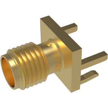
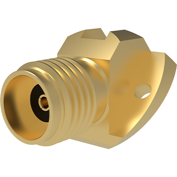
Right-angle mounting saves space: Soldered to the edge of the PCB, the connection direction is perpendicular to the PCB plane, significantly reducing the internal Z-axis height of the device, which is the cornerstone of ultra-thin, compact design.
Through-hole soldering for reliable connection: The terminals are through-hole soldered (THT), with the solder joints located on the other side of the PCB, providing a strong mechanical fixation and excellent electrical connection reliability, especially suitable for environments subject to a certain degree of vibration or stress.
Rugged structure, stable and durable:
Shell Material: Usually made of high performance engineering plastics (e.g. LCP, PBT, PA) with excellent high temperature resistance, flame retardancy (UL94 V-0 compliant) and dimensional stability.
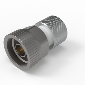
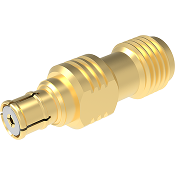
Terminal materials: Made of high conductivity copper alloys (e.g. phosphor bronze, brass) with surface plating (gold, tin or silver) to ensure low contact resistance, excellent corrosion resistance and solderability
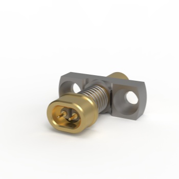
Locking design: Integrated and reliable locking (such as snap type, screw fixing type), to prevent accidental loosening during insertion and mating, to ensure a durable and stable connection.
Guiding structure: Precise guiding column or guiding slot design ensures smooth and accurate mating process and avoids terminal damage.
Signal and Power Transmission: All types of signals (data, control) can be transmitted as well as different levels of power connections, depending on the number of pins, spacing and terminal design.
Environmental Resilience: Designed to meet the environmental requirements of industrial or consumer applications, with a wide operating temperature range (typically -40°C to +105°C or higher) and good resistance to vibration, shock and chemicals
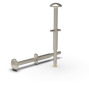
Flexible Configurations: Available in a variety of pin counts (e.g., 5, 10, 15, 20, 30, 40, etc.), pitches (e.g., 1.0mm, 1.27mm, 2.0mm, 2.54mm, etc.), and stacking heights to accommodate a wide range of design needs. Available in straight (Solder Tail) or right angle terminal designs.


 199 5103 1313